So you want a Stratum 1 NTP server...
(Standard warning: I’d consider myself an informed amateur in this field, so don’t take anything I say as gospel.)
The Global Positioning System is an amazing piece of technology. In very simple terms, GPS is a constellation of moving satellites which simply broadcast when they are, and rely on you to know where they can be in the sky. Picking up one satellite by itself determines your position to within a hemisphere of Earth. Two satellites reduce that down to a radial line. Three pinpoint you to a specific latitude and longitude (2D fix). And four or more let you pinpoint elevation (3D fix).
To do this with any sort of accuracy, the clocks onboard the satellites must be extremely accurate. GPS atomic clocks use cesium (or more recently, rubidium) as an oscillator, and are theoretically accurate to within 14 nanoseconds. So great, you have a free source of high-precision timekeeping! Just hook up a consumer GPS receiver to your computer and you have a Stratum 1 device, right?
There’s a small problem, in that there’s a lot of uncertainty in getting from the receiver to your computer. The receiver may say “the current time is 01:23:45.000 UTC”, but there’s a (relatively) massive amount of time between “the” and “UTC”. When was it 01:23:45.000 UTC?
The solution is PPS, or 1PPS. It’s simply a high precision pulse, once per second, at the same time (or as close as can be) every second. Usually the PPS pulse is at the top of the second, and then the receiver has the rest of the second to send its data to the computer.
Many modern GPS receiver chipsets support PPS, but almost no consumer devices support exporting it. Take apart nearly 100% of the “mouse” style u-blox USB receivers, and you will often see a PPS solder pad, but nothing to attach to it. The embedded USB TTL chipset just doesn’t support it.
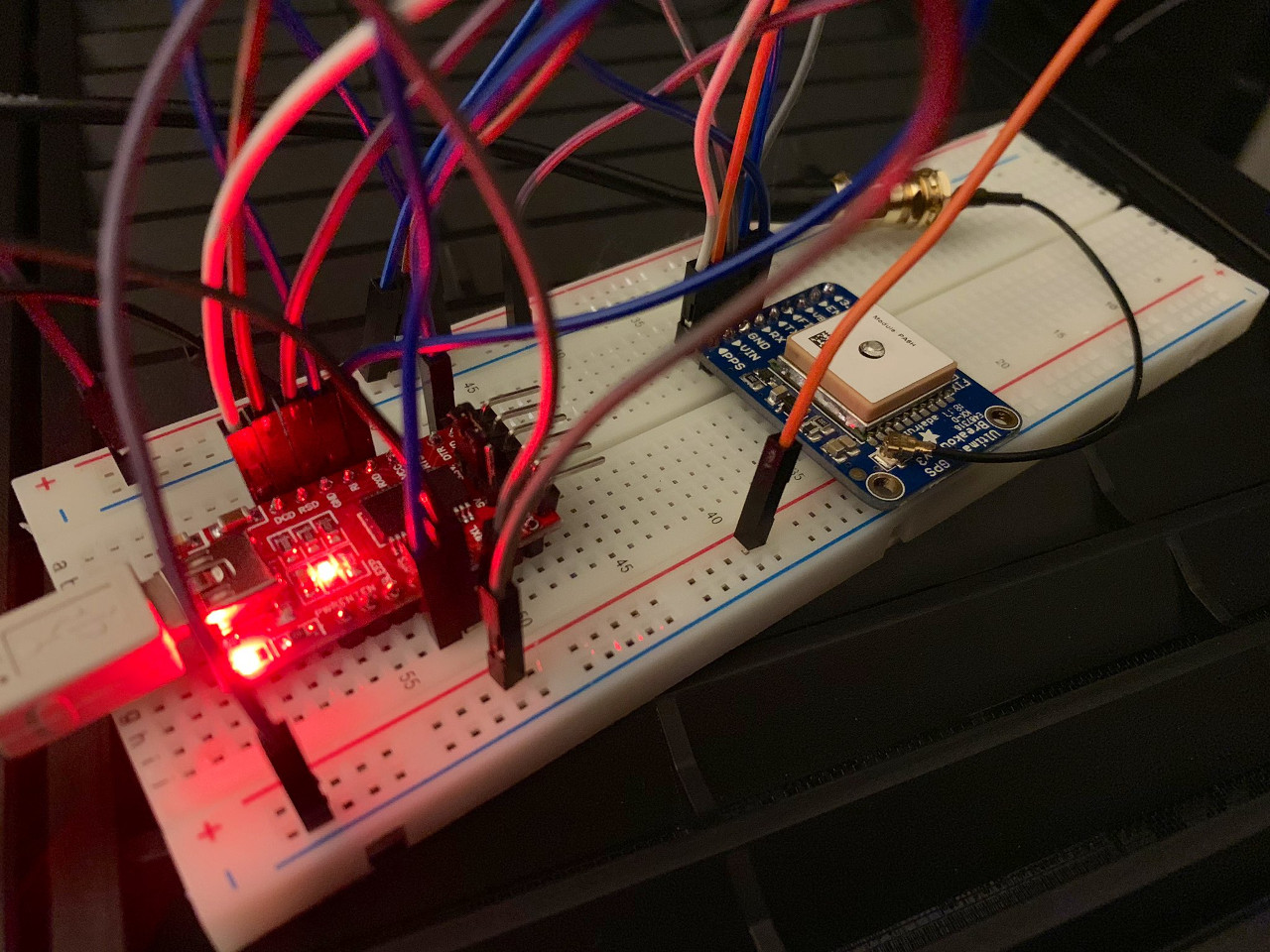 But you can build your own. The FT232R USB chipset has support for emulating all RS-232-style serial control signals, including Data Carrier Detect. DCD’s classic meaning in serial communication is basically “I’m ready to begin sending you something”, so the logic maps well to the PPS concept. This post by Larry Cochrane explains how to pair a $15 GPS receiver module with a $10 FT232R-based USB TTL adapter to get a USB GPS receiver with PPS support. This was the first design I built.
This is fine for a home NTP receiver, but there is a problem. USB is laggy, in the realm of local high-precision timekeeping. (Still better than you could do from an Internet NTP source.) Worse still, it’s unpredictably laggy, i.e. jitter. USB 1 and 2 are packet-based, and it’s not guaranteed packets will arrive over the bus in the exact same amount of time. The average latency from the receiver to the software may be 200 microseconds, but the jitter may be ± 300 microseconds.
If we want to get serious, we need to go old school. RS-232 serial is interrupt-based. An electrical signal comes in, the CPU pauses whatever it’s doing to read it. (In a tiny amount of time; the amount of time lost processing the interrupt is insignificant for modern computers.) And amazingly, the beast of a home server I built late last year — a Ryzen 7 2700X with 64GB memory and 9 hard drives — still has a motherboard with an RS-232 header on it.
Let’s take a moment to discuss RS-232 and TTL. TTL is the language of nearly all modern serial components (such as the GPIO pins on your Raspberry Pi). A one is 3.3V (high), a zero is 0V (low). Fine for high-ish-speed, physically short runs of a few inches. But RS-232 is what home computers used to use for serial communication to devices such as modems. With RS-232, high is anywhere between 3V and 25V, and low is -3V to -25V. Signals between -3V and 3V are discarded as garbage. This was useful for reliable longer-length cable runs.
So we can’t just solder our GPS receiver (TTL) to a DB9 port and plug it into a computer. We need something to actively translate between TTL and RS-232 voltages. There are plenty of TTL to RS-232 DB9 adapters on Amazon and eBay. The problem is they’re almost all based on the MAX232 chipset or similar, which only supports two drivers (transmit from the TTL device to the PC) and two receivers (receive from the PC to the TTL device). 75% of these adapters will implement TX and RX only, and the other 25% will also support CTS and RTS, but no DCD.
The MAX3238 chipset supports five drivers and three receivers, and is designed specifically for full RS-232 translation. As far as I’ve been able to find, there is exactly one manufacturer currently making breakout boards based on the MAX3238: the Pololu 23201a for about $10.
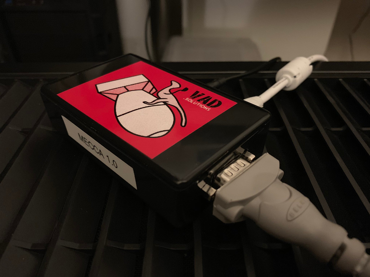
So now, let me present to you MECCA: Measuring Expensive Cesium Clocks in the Air.
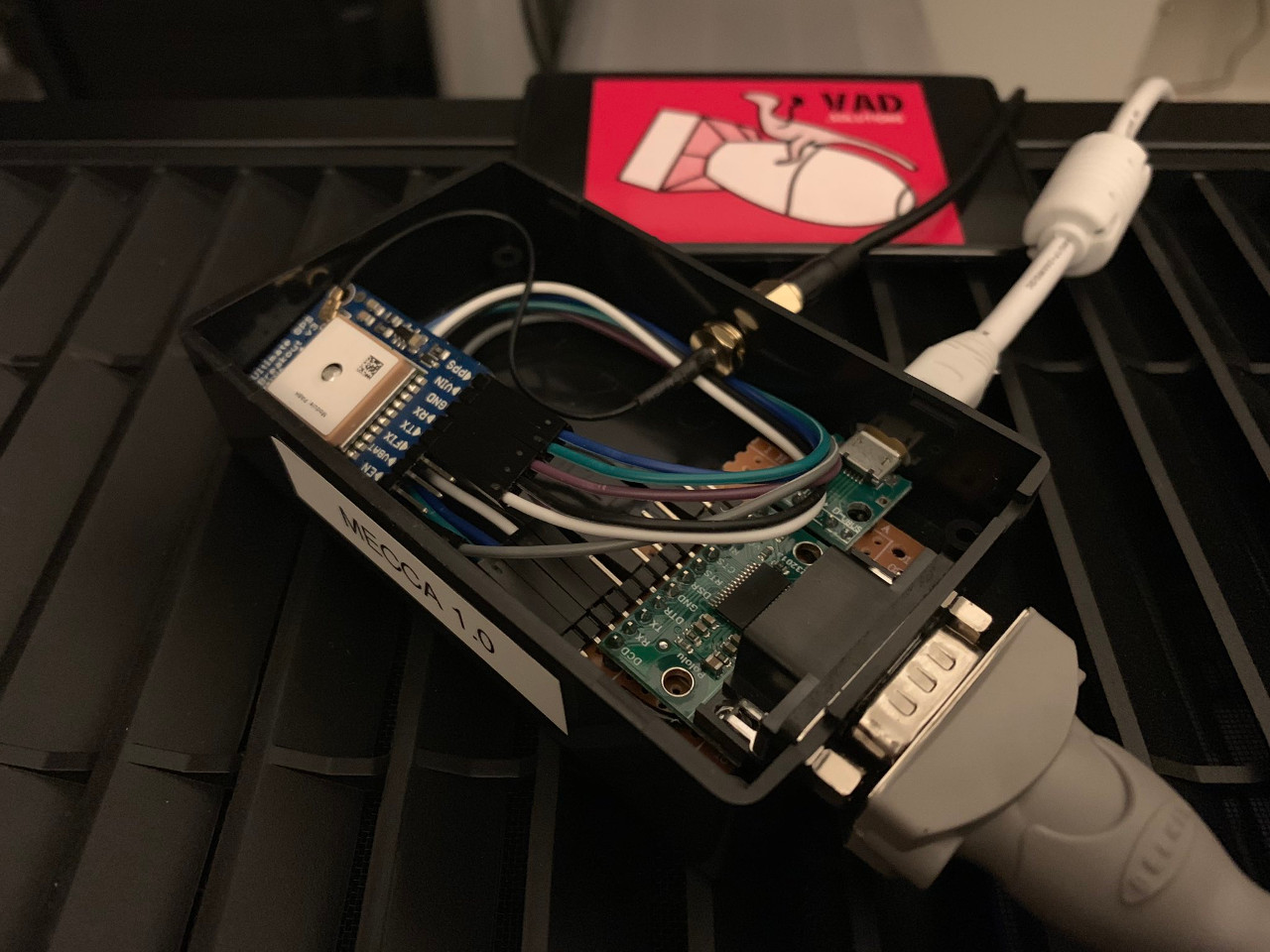
The RS-232 board is the Pololu 23201a. The USB board is a random cheap micro USB header to supply 5V to the GPS receiver, which is an Adafruit Ultimate GPS Breakout. The Adafruit receiver is quite expensive, about $40, but I chose it because it has an automatic external antenna header, something I didn’t find on any of the $15 eBay modules. But if you’re in a relatively open area, the $15 modules with their built-in antennas should be fine.
The receiver has a 3.3V regulator which drives the TTL logic, but also powers the RS-232 board. It’s a pretty simple schematic; the hardest part was soldering the various VCC bridges (needed to keep DSR, CTS and RI high) on the breadboard connecting the RS-232 and USB boards to fit in the project box. (I left the GPS receiver modular since it’s the most expensive component of the setup.)
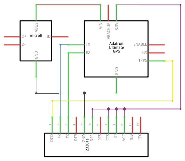
One thing to note if you go for the $15 bare module: The “enable” pin must also be tied to VCC to enable it. On the Adafruit module, “enable” is pulled high by default and can be tied to ground to disable it.
If you wanted to go more versatile, you could build something which supports USB or RS-232:
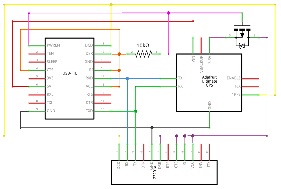
FT232R-based USB converters support “PWREN”, which is high when the converter has power, but goes low when the converter actually has USB communication with a host. This can switch a P-channel MOSFET to VCC on the RS-232 converter, so it’s only active when there’s simple USB power. The only reason I didn’t build this is because fitting it all in a small project box would be tight (and I didn’t happen to have a suitable MOSFET at the time).
Now that you have a PPS-capable receiver, you’ll need gpsd which will interface with ntpd. This gpsd page goes into excruciating detail about the theory and the operation, so I won’t go into the details here. My final ntpd configuration is the standard ntp.org pool config (ntpd works best with other peers to act as sanity checks), plus the following:
# GPS Serial data reference (NTP0)
server 127.127.28.0 minpoll 0 maxpoll 0 noselect
fudge 127.127.28.0 time1 0.521643 refid GPS

# GPS PPS reference (NTP1)
server 127.127.28.1 minpoll 0 maxpoll 0 prefer
fudge 127.127.28.1 refid PPS
I wouldn’t worry too much about fine-tuning the GPS reference. My offset (“time1”) is 521.643ms, but the jitter can be up to 60ms, so I’ve explicitly told ntpd to track it but not to consider it (“noselect”). Even if I didn’t explicitly specify “noselect”, it would eventually work out that the jitter is garbage and ignore it (with an “x” in “ntpq -p”). The kernel PPS feed is the high-precision component, and has an average jitter of about 7 microseconds.